The new student union at Florida’s Embry-Riddle Aeronautical University follows a form inspired by birds in flight. For the engineers, translating that vision into a series of exposed structural systems involved considerable cantilevers and creative designs.
A bird in flight was, appropriately, the inspiration for the new Mori Hosseini Student Union at Embry-Riddle Aeronautical University. Located in Daytona Beach, Florida, adjacent to the Daytona Beach International Airport, Embry-Riddle focuses on aviation and aerospace education along with business, engineering, and other disciplines. The roughly 180,000 sq ft student union — named for a prominent alumnus, donor, and chair of the university’s board of trustees — was designed by ikon.5 architects and engineered by the international engineering firm Thornton Tomasetti. Described by the architects as an “aeronautical athenaeum,” the new student union houses student meeting spaces, a library, an amphitheater, a cafeteria and food vendors, student government offices, common areas, and other administrative spaces. The structure of the $70 million, four-story building features a soaring, curving design with multiple cantilevers. These include the supports called wing beams that help create a roof overhang with cantilevers up to 25 ft and a spine girder that runs the full length of the building footprint, cantilevering approximately 50 ft.
Cantilevers seemed a natural extension of the avian theme, says Chris Christoforou, P.E., LEED AP BD+C, a principal in the Newark, New Jersey, office of Thornton Tomasetti. In fact, cantilevers were “the first thing that came to mind” for Christoforou once he knew the building design represented a bird because to him, the basic shape of a bird features a series of cantilevers. “The beak of a bird is a cantilever, the tail is a cantilever, the wings are cantilevers,” he explains. And once he determined that there would be multiple cantilevers in the design, it was clear to him that the ideal material with which to build this birdlike building was steel.
“Nothing can get you the depth-to-span ratio that steel will,” Christoforou says, adding that steel was also much easier to work with than concrete because it would not need shoring or formwork. At the same time, steel can be more complicated to bend or curve into shapes than concrete, he adds. As a result, the engineers and architects worked together closely to “develop very creative details” to generate smooth surfaces for the roof structure, without relying on breaks, segments, or facets, Christoforou says.
Intended as a signature structure on the Embry-Riddle campus, the student union includes the 120,000 sq ft main building with the curving roof as well as an adjacent, two-story, 60,000 sq ft building with a more conventional design that serves as an events space. Separated by an expansion joint, the two steel-framed buildings required approximately 2,000 tons of steel, with many of the most critical support systems exposed to view.
The extensive use of exposed steel made Christoforou feel like the proverbial “kid in the candy store,” he says. “There’s nothing better for a structural engineer than to see his work exposed!” But with that exposure also came challenges. “When things are exposed and expressed, when they become a feature in the architecture, nothing can be left to chance,” Christoforou says. For example, when an engineer designs connections between, say, a beam and a column in other buildings in which such features will be hidden, it is fine to use large bolts or welds that “do their job efficiently but aren’t aesthetically pleasing,” he says. “But if this column connection will be visible, within a few feet of where a person is standing, it has to look right; it has to look nice. The bolts need to be symmetrical, and the welds must meet a different finish standard.”
Such details are not always within the engineer’s control, of course, which is why the design team created 3D computer models that focused on select, prominent details, such as the points of intersection between girders and columns or other aspects that were critical to maintaining the architect’s vision. These models were included as part of the deliverables given to potential contractors, Christoforou says, which was the design team’s way of telling contractors that “when you bid the job, this is how the final product should look.”
Such models proved extremely useful in helping contractors understand the complex geometry of the roof, which curves in both the north-south and east-west directions, almost like a turtle’s shell, Christoforou says. “We couldn’t translate it into x-, y-, and z-coordinates on a blueprint — it wouldn’t do justice to the design,” he adds.
To create these 3D models, the design team relied on several software systems, including Tekla Structures, manufactured by Trimble Solutions USA Inc., of Kennesaw, Georgia, and Grasshopper 3D, part of Rhinoceros 3D, manufactured by Robert McNeel & Associates, of Seattle. Revit, manufactured by Autodesk Inc., of Mill Valley, California, was also used to size key structural elements. Although Christoforou had given contractors 3D models before, the student union project was the first time he had used such models with the architect specifically to help contractors generate the proper geometry of a structure. During the construction phase, the design team periodically visited the fabrication shops “to answer questions and observe the (fabrication) of the steel before arrival on-site,” according to an ikon.5 description of the project.

Thornton Tomasetti also created a set of guidelines to help the contractor and subcontractors erect the structural elements of the student union in the proper sequences — on this project, quadrant by quadrant rather than floor by floor — to avoid imposing too much loading on any point too early, Christoforou says. Similar guidelines have proved useful to the firm in its design of sports facilities, which also often feature large cantilevers, long spans, and complex geometries, Christoforou adds.
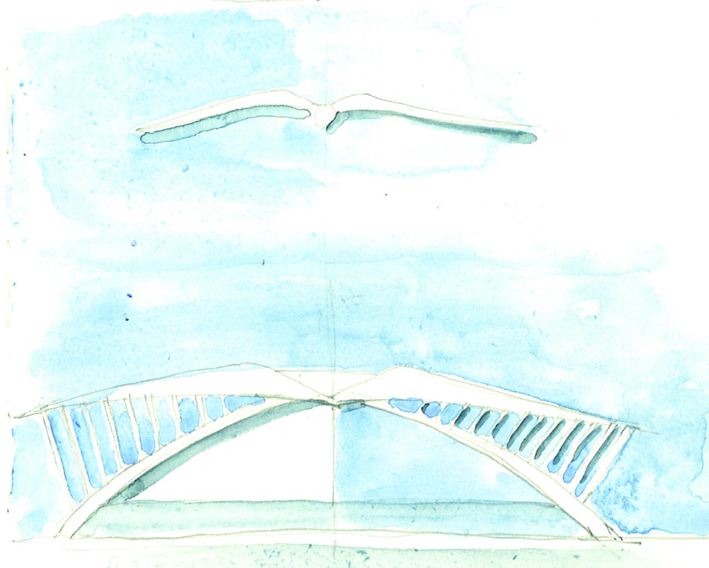
On the architect’s website, a soft-blue-and-white watercolor image compares the student union’s curving, bowed roof with the wide wings of a large white bird, floating on the wind overhead. Mimicking where the bird’s spine would be is the spine girder of the building, a 200 ft long element that follows the longitudinal axis of the building. Together with a series of W30 cantilevered wing beams, the spine girder supports a glass skylight, “allowing the students of aviation the ability to look skyward while inside,” according to the ikon.5 description. The cantilevering spine girder consists of two side-by-side, wide-flange shapes that extend beyond the facade.
The long span and other factors made it impossible to use a single wide-flanged beam, Christoforou says. Instead, a pair of W24 beams laced together by a top plate provided the necessary strength and stiffness while also minimizing the overall depth of the section. Channels on top of the two wide-flanged beams also support the main gutter that runs along the middle of the roof.
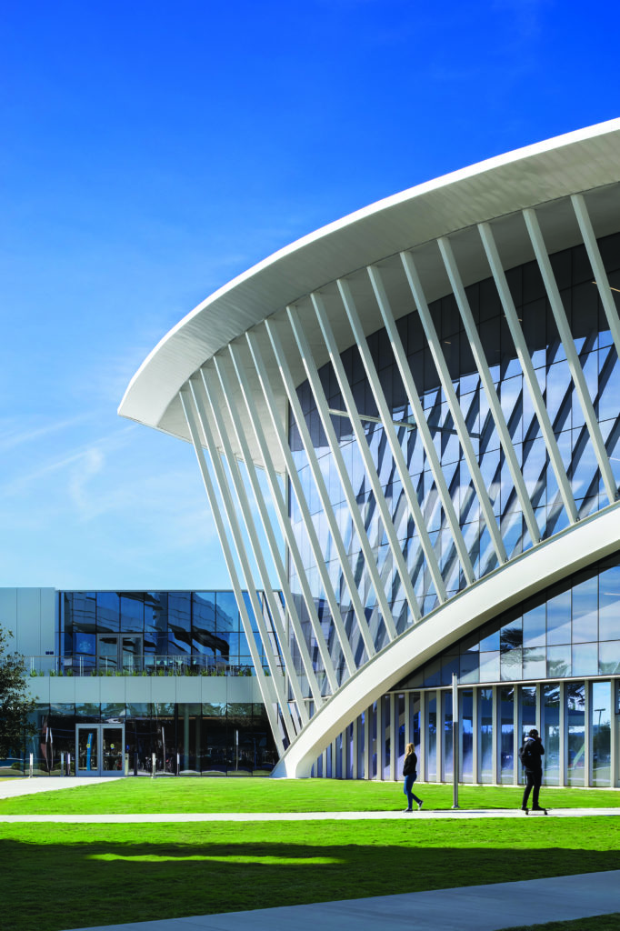
The deflections of this giant girder and the accompanying wing beams that help create the roof overhang are controlled by four external arches — composed of 4 ft deep built-up box girders — and a series of vertical struts. Extending from the ground to the roof at its northern and southern ends, the arches curve in plan and elevation. Welded to the topside of the arches and connected to the underside of perimeter steel beams, the steel struts are made from 12 by 8 in. hollow structural sections (HSS) and vary in length to follow the roof geometry. The connections of the struts to the roof beams featured slotted holes to permit roof deflection during construction.
The struts add to the student union’s avian imagery, conveying “a featherlike quality,” according to ikon.5. Although originally intended as an architectural feature, the struts also serve as structural supports that help tie down the roof and resist wind uplift. Hurricane-level winds can reach up to 145 mph at the site.
The main building’s framing system includes conventional braced steel frames and a composite floor system. The floor comprises 6.5 in. thick lightweight concrete on a 3 in. metal deck that spans approximately 11 ft between W18 floor beams. The W18 beams are supported by W21 girders that are supported by round HSS columns on a 22 by 34 ft grid.
Three monumental stairs curve in both plan and elevation. The stringers of these signature elements were created with curved W16 beams with side plates. Other stairs are located near the perimeter of the building and are enclosed by steel braced-frame cores that feature channel sections for the stringers and landings that are suspended from the floor framing with rods. Elevators are also located in the northwest quadrant of the structure.
Within the main building, a four-story open space contains an atrium and stepped seating areas that overlook the ground-level lobby. Because extensive openings were required in the slabs on levels two and three to create the atrium, many of the main girder beams were cantilevered from the HSS columns. The creation of the moment connections through these HSS columns was a challenge, Christoforou adds, because the HSS walls were generally thinner than the typical wide-flanged column, and thus it became difficult to transfer the forces. Varying from five-eighths to three-fourths of an inch, the thicknesses of the HSS column walls were critical to the strength and stiffness of the moment connections. The solution involved cutting the columns in two places to install steel plates at the top and bottom flanges of the beams that had to pass through the columns. With these connections, the moment transferred from beam to beam by way of the flange plates without requiring the forces to be transferred through the columns themselves.
Cantilevered girders made from built-up sections of wide-flanged beams were cut to follow the geometry of the stepped seating in elevation. Secondary beams, curved in plan, supported the stepped areas, which featured similar construction to the floor framing system: lightweight concrete on metal deck.
The multistory amphitheater was made with cold-formed construction above the structural slab. It required considerable coordination to identify the locations of vertical posts to make sure the posts aligned with steel beams below. Certain areas within the student union, such as the library, also required strengthened slabs and slab depressions to accommodate the shelf stacks. The heavily glazed facades required mullions strengthened by vertical steel struts composed of HSS elements with half-inch-thick side plates.
A roof terrace on the second floor provides students with views of the adjacent runway of Daytona Beach International Airport and rocket launches from the Kennedy Space Center at Cape Canaveral, roughly 50 mi to the south, according to ikon.5.
Because the bearing capacity of the soil was 3,000 psf — according to the geotechnical engineer, Universal Engineering Sciences — the foundations of the student union building featured conventional slab-on-grade construction. Typically 6 in. thick, the slab featured certain 8 in. zones to accommodate the higher loads of certain mechanical system spaces and other specific areas with greater demands. The HSS columns were supported on isolated concrete footings that varied in size from 5 by 4 ft to 15 by 15 ft, and the braced-frame cores were supported on combined footings to resist uplift forces. There are no underground spaces.
The roof’s complex geometry and architecturally exposed structural steel elements included the main spine beam that is aligned in the north-south direction and a series of moment frames in the east-west direction. A moment connection links the cantilevering spine beam to the HSS columns, which extend to the roof. The roof features a 3 in. deck supported by W12 secondary purlins that curve in elevation and are spaced approximately 6 to 7 ft apart on center. The HSS columns support the wing beams which, in turn, support the purlins.

The stability of the roof is provided by a combination of moment frames — composed of the roof girders and columns — the cantilevered action of the columns from the level four columns, and the indirect bracing action of the external arches. The detailing of the roof was also especially challenging, Christoforou recalls, but the Tekla models and documentation of the main steel connections enabled the architect to clearly visualize and understand the final appearance of these connections. These resources also greatly helped the contractor during the assembly of these connections on-site, he says.
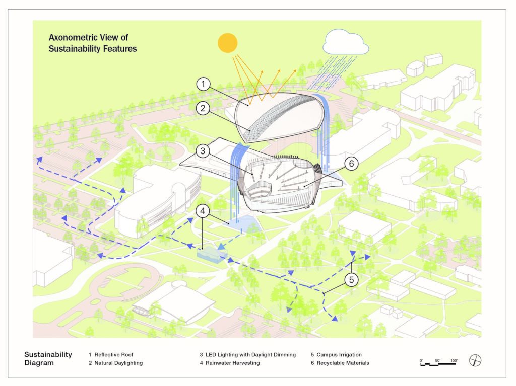
Designed as a high-performance, resource-efficient building, the student union features various sustainable details. For example, the enormous curving roof provides shading from the harsh Florida sun while also collecting rainwater and siphoning it to below-grade cisterns for storage and later use in campus irrigation. The lighting design “reinforces and highlights the architectural forms and spaces that are inspired by flight,” while also enhancing “the airiness of the structure,” according to ikon.5. “In reinforcing the organic architectural expression of the spaces, the overall effect creates a glowing beacon at the campus entry.”
For Christoforou, working on the Mori Hosseini Student Union has been one of the high points of his career. It was not the largest project he ever worked on, he says, “but it was so much fun doing it!” Moreover, the vision, creativity, and collaboration with the architects at ikon.5 “was truly inspirational to me,” he stresses. Christoforou especially acknowledges the contributions of his former colleague Iliana Karagiannakou, P.E., who served as Thornton Tomasetti’s project engineer on the Mori Hosseini Student Union. Karagiannakou has since left the firm.
The exposed structural steel also adds a personally rewarding aspect to the project. “When you walk through the building, you know you touched every element,” Christoforou says. “You see something (and) you know that’s not by accident; that’s how we drew it. It’s what makes this one special to me!”
PROJECT CREDITS Client Embry-Riddle Aeronautical University, Daytona Beach, Florida Architect ikon.5 architects, New York City Structural engineer Thornton Tomasetti, Newark, New Jersey, office Mechanical, electrical, and plumbing engineering and fire protection engineering OCI Associates, Maitland, Florida Civil engineer Parker Mynchenberg & Associates Inc., Holly Hill, Florida Geotechnical engineer Universal Engineering Sciences, South Daytona, Florida General contractor Barton Malow Co., Orlando, Florida Landscape architect Prosser, Jacksonville, Florida Lighting designer Fisher Marantz Stone, New York City
This article first appeared in the January/February 2021 issue of Civil Engineering as “Flight Plan.”
The cover photograph is courtesy of Brad Feinknopf.


