

The addition of hydroelectric power to the existing Red Rock Dam on Iowa’s Des Moines River presented engineers with the opportunity to use an untapped resource to generate clean and reliable power. Although the original design of the dam had not anticipated hydropower, the changes recently enacted will provide electricity to the surrounding communities for the next 100 years.
The Red Rock Hydroelectric Project is an example of a public power utility that listened to its stakeholder communities. Designed primarily for flood-control purposes, the Red Rock Dam was constructed in the 1960s on the Des Moines River and Lake Red Rock, near Pella, Iowa, by the U.S. Army Corps of Engineers. Although provisions for hydropower had not been included in the original construction, new facilities added to provide hydropower look and feel as if they were part of the plan all along. The new additions are expected to generate power for the next 100 years.
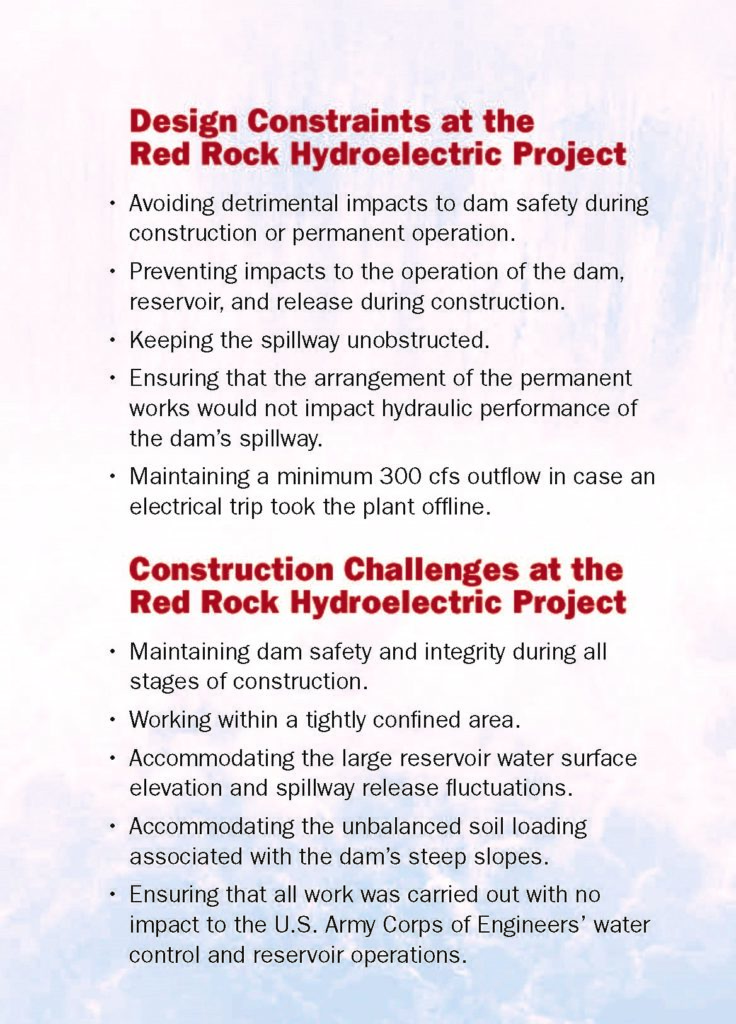
But the effort was not easy. The project had to overcome numerous challenges, most notably dam safety concerns because the project had to be constructed immediately adjacent to the operating spillway.
Operated by the Corps on behalf of the federal government, the dam is an earthfill structure with a chimney filter and blanket drain. It features a central concrete control structure consisting of 13 adjoining monolithic segments — known as gravity monoliths — that house 14 sluice gates and five tainter gates. The dam has an overall length of 6,260 ft and a height of 110 ft. A county highway traverses the length of the dam along the crest.
Power plan
The hydropower development rights — licensed by the Federal Energy Regulatory Commission — are held by the Western Minnesota Municipal Power Agency, a municipal corporation and political subdivision of the state of Minnesota. The agency is represented on this project by Missouri River Energy Services, based in Sioux Falls, South Dakota. The international engineering firm Stantec served as the owner’s engineer and designer of record.
The licensed location for the project involved a site immediately adjacent to the spillway near the center of the dam and on the northeast side of the river. This position was chosen, in part, because of concerns over the soluble gypsum deposits near the left abutment of the dam as one looks downstream. Although the location avoided potential seepage issues associated with the gypsum deposits, the development of a detailed design at that site required considerable creativity. The goal was to prevent any negative impacts to spillway operations and maintain dam safety throughout construction.
The plan for the hydropower project underwent several iterations. The original concept, for example, included three concrete penstocks, which are large diameter water-conveyance conduits. But after a Stantec review — intended to address constructability issues and improve project performance — the plan was revised to two larger penstocks, each centered within one of the concrete gravity dam monoliths. This change maximized the concrete cover relative to the monolith joints and reduced the width of the intake structure. The decision also enabled the wire saw-cut penetrations through the concrete monoliths for the penstocks to be self-supporting.
Additionally, the use of two identical turbine generator units rather than three units of varying capacities offered several benefits, including:
- Reducing the width of the powerhouse.
- Minimizing the widths of the associated excavations in the embankment dam and its foundation.
- Maximizing power generation.
- Simplifying unit operations and maintenance.
The engineers selected vertical Kaplan-style turbine generators, which use rotating blades to optimize efficiency under a wide range of discharge flows and pressure head conditions, for the project. These were designed to maximize annual power generation rates based on an assessment of the historic reservoir level and discharge data. Each unit has a rated capacity of 18 MW but can generate up to 27.5 MW, for a total generation of up to 55 MW under high flows. The original concept also included a reinforced diaphragm wall with tieback anchors and a sheet-pile extension to support the embankment along the left side of a new intake channel.
However, there were concerns that installing tieback anchors through the embankment could lead to hydrofracturing in the core of the dam. Moreover, the tieback anchors themselves could become a long-term maintenance concern. So instead, the design was modified to include a heavily reinforced diaphragm wall composed of large T-shaped cantilevered elements. This eliminated the use of anchors entirely. Additionally, the wall was curved away from the channel to improve hydraulics within the approach channel, eliminate the need for a sheet-pile wall, and avoid long-term issues associated with pile corrosion and strength loss.
Rules and regulations
Although necessary, the laws and regulations surrounding the hydropower licensing process can present challenges to getting projects started. The Red Rock project, for instance, required approval of the U.S. Army Corps of Engineers’ Rock Island District, the Federal Energy Regulatory Commission, and an independent external peer-review panel. Additionally, private developers who intend to add hydropower need to satisfy all laws and regulations governing the use of water, wildlife conservation, historic preservation, and power distribution.
For these reasons, design reviews assessed compliance with provisions in the hydropower license, such as the need to minimize intake velocities to avoid fish entrainment, in addition to dam safety matters. As part of the design approval process, an analysis was conducted to identify potential failure modes for all phases of construction and for conditions once the permanent works were in place and to develop mitigation and monitoring measures where appropriate.
The project not only required permits related to impacts to the “waters of the United States,” as referenced in the Clean Water Act, but also another permit for the modification of a federal structure. This permit was based on a detailed design and supporting analysis for the phased construction of the project.
Layout and operation

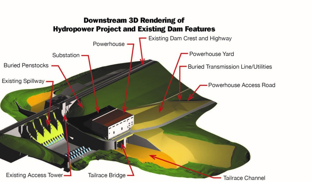
The layout and operation of the Red Rock Hydroelectric Project is relatively simple. Water flows from the reservoir through the intake structure on the upstream side of the dam. The penstocks convey the water from the intake structure downstream through the dam to the powerhouse, which houses the turbine generator units. Within the powerhouse’s water passages, water flows horizontally around a structure known as the spiral case and through the wicket gates. The spiral case is the part of the powerhouse in which the water spins the turbine blades to turn the rotor shaft. The turbine shaft, which is connected to the blades, turns the rotor inside of the stator to generate electricity. The substation, which includes generator step-up transformers, is located on the upstream side of the powerhouse and connects to a 69 kV transmission line.
To make all this happen, however, large civil structures were required, including:
- A 69 ft high cantilevered retaining wall that uses 130 ft tall T-shaped concrete diaphragm walls socketed into rock. This wall retains the existing embankment dam along the new intake approach channel.
- A second diaphragm wall along the axis of the embankment dam that formed a seepage cutoff during construction and continues to serve this function now. The cutoff wall is 100 ft long and ties into the end of the concrete gravity dam.
- An intake structure 99 ft high by 112 ft wide by 60 ft deep, containing two water passages, a trash rack on the upstream face, two emergency wheel gates, and bulkhead slots and storage.
- Two penstocks, 280 ft long, with an inside diameter of 21 ft. Both penstocks penetrate the concrete gravity dam monoliths and are lined in steel downstream of the dam.
- A powerhouse measuring 150 ft wide by 98 ft deep by 144 ft high.
Located at the toe of the dam, adjacent to the original stilling basin, the powerhouse features the two turbine generator units, an overhead crane, the balance of the plant equipment, and bulkhead slots and storage. It also includes a 48 in. diameter steel bypass conduit to provide a minimum flow if the units experience an electrical load rejection, or “trip,” during operation. Jet nozzles incorporated into the bypass can be used to satisfy the dissolved oxygen requirements of the hydropower license. Stantec has worked on several projects similar to Red Rock, all of which are located at existing dam sites. Although these previous projects were similar in general scope, the unique site details made each project different from a civil engineering perspective, with Red Rock being perhaps one of the most challenging.

When hydropower is added to an existing dam, the new facility is typically constructed through an abutment to minimize impacts to the existing dam. Teams use any provisions, if available, for future hydropower that had been included in the original construction, such as extra penstocks and bays within the dam. But as noted earlier, the Red Rock Dam had not been designed with such provisions. Moreover, the Red Rock project’s licensed location required significant excavation support, together with a unique cofferdam system so that the hydropower facilities could be constructed within the steep slopes adjacent to the operational spillway.
Because of the design team members’ experience with the permitting and regulatory approval processes, they understood the importance of construction sequence drawings to defining the overall progression of construction so that the integrity of the dam would be maintained throughout all phases of construction. At Red Rock, these construction sequence drawings took on additional importance because the temporary loads associated with the construction staging often controlled the structural design of the permanent structures.
The available information about the subsurface conditions from the original design and construction of the Red Rock Dam was beneficial to the design of the hydroelectric project. Only a limited supplemental geotechnical investigation program was needed, and it focused on confirming soil and rock parameters. But additional data on the bedrock at the site were necessary. This was achieved through borehole pressuremeter testing that determined the modulus of the bedrock, which was critical to the design of the upstream diaphragm wall that retains the dam embankment along the new approach channel.
Upstream risks
The design of the upstream works proved to be the single greatest area of construction risk to the project. The upstream works were constructed on and within the sloping faces of the embankment where it wraps around the gravity dam, both above and below the reservoir levels. Before the start of construction, there were no flat or gently sloping areas from which heavy equipment could operate and no vehicular access to the area of the future intake structure.
The upstream diaphragm wall along the new intake channel had to support a 69 ft tall cut in the embankment dam without anchors while also minimizing deformation that could potentially induce cracking of the dam’s clay embankment. Thus, the wall was constructed using abutting T-shaped elements up to 130 ft tall. These heavily reinforced elements included 5 ft wide stems that extended 16 ft into embankment from the back of the 5 ft thick face of the diaphragm wall, which made them a total of 21 ft across.
The construction sequence for each T-shaped element required three overlapping passes, or “bites,” of the hydromill trench cutter to achieve the design geometry. Each bite consisted of a vertical pass of the 10.5 ft long by 5 ft wide hydromill cutter head from the ground surface to the bottom of the rock socket.
The rock embedment depth of the upstream diaphragm wall was established to minimize deformations and ranged up to 35 ft. Reinforcing cages for each T-shaped element weighed up to 90 tons. A self-consolidating tremie concrete mix with an initial set time of 16 hours and negligible bleed was developed to facilitate the extended duration required to place concrete for each T-shaped element.
Another challenge involved the construction of the intake structure and upstream penstocks in a way that would avoid placing any additional load on the existing spillway approach wall. Ultimately, the solution involved a staged excavation supported by a portion of the upstream diaphragm wall, together with a lightweight concrete work platform. The 70 ft deep intake excavation was supported by a braced secant pile wall socketed into rock. The excavation incurred minimal leakage from the surrounding reservoir.
Similar to the upstream side, much of the downstream work was constructed within sloping fills around the gravity dam, so significant earth-retention systems were necessary.
A braced, earth-retaining wall system — designed via 3D modeling — accommodated the differential loading across the excavation caused by the steep dam slopes. Penstock excavations up to 70 ft deep were designed to minimize deformations of the embankment. Open areas without bracing at the base of the excavation measured approximately 30 ft high by 30 ft wide. These accommodated the installation of the penstocks’ 21 ft diameter steel liners. Increasing the challenge, one of the downstream penstocks featured a horizontal curve that the excavation support had to follow.
A cellular cofferdam protected the riverside of the downstream work area from adjacent spillway flows and the river. This location was closed off by a rockfill dike to allow the powerhouse excavation and construction to proceed in the dry. A secant pile wall with tieback anchors supported the powerhouse excavation and helped minimize deformations along the toe of the embankment dam. In addition, the design team had to determine if controlled blasting could be used to excavate the rock immediately adjacent to the toe of the existing stilling basin wall.
After test blasts verified the proper methods, blasting was performed to within 8 ft of the toe while maintaining acceptable peak particle velocities. This eliminated the need to perform mechanical excavation at that location, as had been envisioned during the initial design approval process.
Because of the extensive and intrusive nature of the numerous excavations into the existing dam, the diaphragm cutoff wall was constructed through the center of the embankment, extending off the end of the dam’s concrete gravity monoliths. This feature was designed to prevent any excavation-induced cracking of the embankment dam from propagating from the downstream to the upstream side. It also addressed the potential for piping (internal erosion caused by seepage) along such features.
Construction challenges
The construction phase, which was bid in 2013 and broke ground in 2014, also presented some unique challenges. The initial phase of upstream construction involved the diaphragm cutoff wall and the upstream diaphragm wall. Once the upstream diaphragm wall was complete, a work platform was created from which to construct the intake and upstream penstocks. Secant piles were then installed to form the cofferdam for the intake structure, and the braced excavation for the intake was completed, along with the concrete placements for the intake structure. The braced excavation for the upstream penstocks began once the intake excavation was complete. The initial partial penetrations into the upstream side of the gravity dam were then completed, followed by the concrete placements for the upstream penstocks.
The initial phase of construction for the downstream work featured the downstream cellular cofferdam and the secant pile wall for the powerhouse excavation. Additional work included the overburden excavation, consolidation grouting around the perimeter of the rock excavation, and controlled blasting and rock excavation. Construction of the powerhouse then proceeded, along with braced excavation for the downstream penstocks. Once the powerhouse was watertight up to the level of the cofferdam protection, the cofferdam was removed, and the tailrace channel excavation was completed and riprapped. Construction and outfitting of the powerhouse continued, as did construction of the downstream penstock.
The substation was constructed along the upstream side of the powerhouse, and the buried transmission line was constructed along and adjacent to the toe of the dam. For the most part, the record documents of the existing dam proved to be accurate — except for one surprise discovered early in the construction phase. Grouting was performed before rock excavation, primarily to strengthen the rock mass but also to reduce seepage inflows during construction. While grouting around the landside perimeter of the powerhouse excavation, the construction team encountered a voided zone in the rock created by previously undetected gypsum. The voided zone had originally been partially infilled with soil and rock fragments yet was still characterized by artesian flows.
These flows came from grout holes and reached volumes of 20 gal. per minute or higher. A combination of extensive cement and chemical grouting was ultimately used to treat the voided rock.
Extensive flooding of the upstream work area in 2018 and 2019 delayed the project. Although such periods of high water made the site attractive for hydropower development, it was not practical to construct a cofferdam to protect against the full range of reservoir fluctuations. The cofferdam for the upstream work areas had been designed to accommodate periods when the reservoir was moderately elevated above normal pool. But the reservoir levels in 2018 and 2019 exceeded that level and remained elevated for several months, delaying completion of the upstream work.
The final penetration through the concrete gravity monoliths for each penstock needed to be timed to avoid the possibility that a flood might cause an uncontrolled release through the tunneled opening in the dam. Once the intake structure was completed, the wheel gates were installed and operational, and the upstream penstocks had formed a watertight connection between the intake and upstream face of the dam, the construction crew began cutting through the monoliths with wire saws so that the two portions of the penstocks could be connected. The intake channel was then excavated and riprapped, the secant piles were removed from the upstream face of the intake structure, and the upstream slope of the dam was restored.
The penstocks were watered up and the wet commissioning of the turbine generator units began in July 2020, followed by the dedication of the completed project on Sept. 2, 2020.
Safety matters
A major lesson learned during the Red Rock project was the importance of having a dedicated dam safety team committed to a robust surveillance and monitoring program during construction, complemented by open communications with stakeholders — in this case, the Corps and the Federal Energy Regulatory Commission. Red Rock presented unique challenges for the surveillance and monitoring of the existing dam through all stages of construction. Safety monitoring of the large excavations into and penetrations through the dam required a unique and flexible approach. The team had to evaluate the performance of excavation support systems, other temporary works, and the existing dam.
By combining different instrumentation — including survey points, inclinometers, piezometers, pressure cells, and strand load sensors — data could be cross-checked to increase confidence in readings, and deformations could be evaluated in multiple ways and compared with anticipated behavior. The system also provided redundancy in case of instrument malfunction or construction interference. Threshold values and action levels for each instrument were based on analyses of the critical loading conditions for the various stages of construction.
During all phases of the project, the design team, the owner, the government agencies, and the contractors worked collaboratively to address design and construction challenges. From the beginning of the project, the simplicity of the final layout belied the numerous innate dam safety challenges of the effort. As the design evolved, the interconnected nature of the staged construction for each project feature became more apparent. The solution was an iterative approach that enabled the team to finalize the construction sequencing requirements and design the structures for the temporary and permanent load cases during all stages of construction.
Stakeholder input and buy-in was crucial to the success of the project. It improved the monitoring of dam safety during construction and served to address unexpected issues as they arose. While more patience was needed than originally envisioned to address regulatory constraints and unexpected construction issues, the project has been received well by the Western Minnesota Municipal Power Agency, Missouri River Energy Services, and most importantly, the more than 18,000 homes in the surrounding communities, which can expect a reliable source of energy for decades to come.
PROJECT CREDITS Dam operator U.S. Army Corps of Engineers Hydropower developer Western Minnesota Municipal Power Agency, represented by Missouri River Energy Services, Sioux Falls, South Dakota Owner’s engineer and designer of record Stantec, Chicago General contractor Ames Construction, Burnsville, Minnesota Turbine generator unit designer and manufacturer Voith Hydro, York, Pennsylvania Substation and transmission line designer DGR Engineering, Rock Rapids, Iowa Specialty geotechnical subcontractor for diaphragm walls and secant pile walls Case-Bencor Joint Venture, part of Keller North America, Hanover, Maryland
This article first appeared in the March/April 2021 issue of Civil Engineering as “Red Rock Power.”


What was the total cost of the project?